Setting Up Modular Static Set (Killing Floor 2)
MODULAR STATIC SET
The Modular Static Set is a series of interchangeable static meshes which can be combined to block out map areas in lieu of UDK's Binary Space Partitioning (BSP) geometry. The individual meshes are based on a 320 UU (Unreal Units) square, with each section being unwrapped to fill the entire square UV space. In this way, if a tiled texture is used within the applied material, the modular meshes will tile seamlessly when placed next to each other. However, in order for the system to work, most meshes SHOULD NOT BE ROTATED! Doing so will change the UV orientation between various pieces, creating seams.
Organization
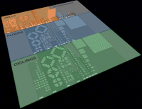
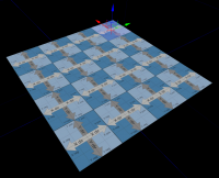
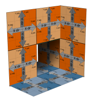
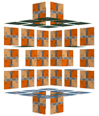
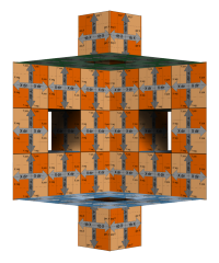
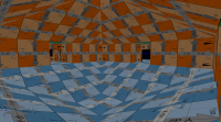
The set is composed of individual static meshes which fall into the following broad categories: FLOOR meshes, CEILING meshes, WALL meshes and MISC meshes (e.g., Stairs, Railings, Ramps, Doors, Windows, etc.). The first three of these have color-coded, double-sided default materials: Blue, Green and Orange, respectively (see Fig. 1.).
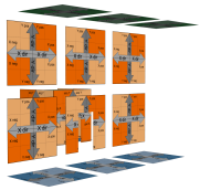
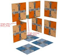
A color-coded map with the majority of the Modular Static Set pieces organized and labeled is available, called Mod_Tools_Modular_Template (see Fig. 2.). Here similar pieces are grouped and oriented for easy reference.
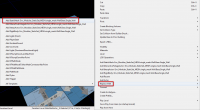
Specifically, within the “Env_Modular_StaticSet_MESH” package, the meshes are initially grouped by the categories mentioned above: Ceiling, Door, Floor, Ramp, Stairwell, Wall and Window. Within each of these categories, there are subgroups, such as: Base, Half, Quarter, Angle, Bevel, Corner, etc. Selecting and expanding these subgroups helps limit the number of meshes displayed within the browser, which makes finding a particular modular piece much easier. For example, within the “Wall” category, expanding the “corner” subgroup followed by the “corner_in” subgroup and the “door” subgroup, displays only wall pieces terminating into concave corners that contain doors.
Methodology
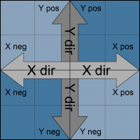
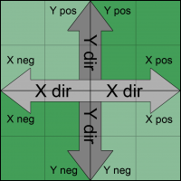
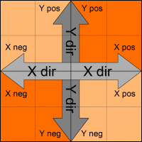
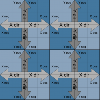
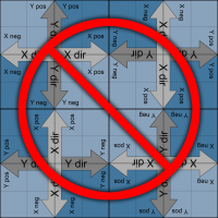
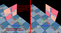
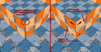
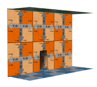
The default textures visually indicate the UV orientation of a particular piece based on X and Y coordinate axes. In order for the tiling to be seamless, the X and Y directions of matching category pieces must be aligned with the positive (“pos”) direction connecting to the negative (“neg”), and vice versa (see Fig. 3.).
Lineup
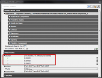
In fact, best way to begin a map is to select a basic floor piece (i.e,. 'Env_Modular_StaticSet_MESH.single_mesh. Floor.Base.Single_Floor') from the Content Browser, right click and add it into a new map, zeroing out its Location values. To do this, select the floor piece, click F4 (to bring up the “Properties” window), and expand the “Movement” tab. Click on the field next to “X,” type “0” and hit Enter. Repeat for the “Y” and “Z” fields (see Fig. 4.).
Location
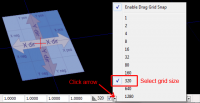
This will ensure that the floor mesh will work with the default modular set grid setting (i.e., 320 UU). To change your grid setting, click on the small down arrow at the bottom of the main Unreal window and select “320” (see Fig. 5.). If you need to change the grid to a smaller size (e.g., when using Half or Quarter sized meshes, for example), repeat the above steps, selecting the desired grid size.
Grid Size
With the floor mesh selected, activate the “Translation Mode” widget, hold the Alt key and drag along either the X or Y direction to duplicate the floor. The edge of new floor piece should snap up to the edge of the previously placed piece. Repeat this until you have a section of floor (see Fig. 6.).
Translation Widget
If no individual floor pieces were rotated, then the UV orientation should be consistent across all of the duplicated floor pieces. At this point, if a material using a tiled texture is dragged and dropped onto all of the selected floor meshes, it will tile seamlessly across all of them.
In order to create a wall section, select one of the floor meshes and duplicate it by right clicking, selecting “copy” followed by right clicking and selecting “paste” (or simply pressing Ctrl+”C” followed by Ctrl+”V”). With the floor piece selected, find the basic wall piece (i.e., 'Env_Modular_StaticSet_MESH.single_mesh.Wall.Base.Single_Wall') in the Content Browser, right click on the duplicated floor and select “Replace With” and “Add StaticMesh: Env_ Modular_StaticSet_MESH.single_mesh.Wall.Base.Single_Wall” (see Fig. 7.)
Replace With
This Copy/Paste/Replace methodology is essential when building maps using the Modular Static Set because, assuming the first placed mesh's Location values were zeroed out, all other meshes are derived from duplicating (and replacing) the initial one. Therefore, in general, all of the map pieces will remain snapped to the default grid setting.
If the newly created wall piece is not aligned in the desired direction, with the wall piece selected, tap the spacebar to toggle the widget into “Rotation Mode” and simply drag the widget to align the wall as desired (see Fig. 8.). [NOTE: this is one of the few exceptions to the DO NOT ROTATE rule mentioned above]
Rotation
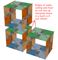
[NOTE: you may notice that the bottom edge of the wall piece does not line up with the edge of the floor piece—this is by design and the reasons for this will be described later]
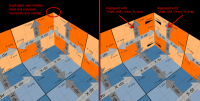
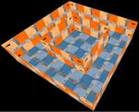
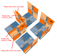
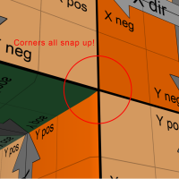
Then, as with the floor pieces, the wall mesh can be duplicated using the Alt key+drag “Translation Mode” widget as before. Eventually, however, you may require that the wall meet another wall at a corner. If this is a concave “corner in” (see Fig. 9.), then open the Content Browser, expand the “Wall” group of the Modular Static Set package and expand the “corner,” “corner_in” and “Base subgroups. Replace the left wall mesh with “Single_Wall_Corner_In_ Xpos” mesh and the right wall mesh the “Single_Wall_Corner_In_Xneg” mesh. This will cause the corners to snap together. Additionally, the default material for these “corner in” pieces have black arrows labeled “corner” which visually reinforce that the correct pieces were chosen.
Corners
Conversely, if the corner is a convex “corner out” (see Fig. 10.), then expand the “corner, “ “corner_out” and “Base” subgroups under the “Wall” group. Replace the left wall mesh with “Single_Wall_Corner_Out_Xpos” mesh and the right wall mesh the “Single_Wall_Corner_Out_Xneg.”
Before long you can quickly produce some basic corridors (see Fig. 11.).
Corridors
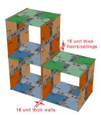
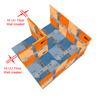
The reason the edges of the walls do not connect to the edges of the floor and ceiling pieces is due to an 8 UU offset built into the walls, floors and ceilings. In this way, the Modular Static Set pieces can be placed directly next to each other, automatically creating 16 UU thick walls and floors (see Fig. 12.)
Offsets
Because of this built-in offset, two “corner in” pieces can be placed next to two “corner out” pieces to create a room directly adjacent to a corridor (see fig. 13.).
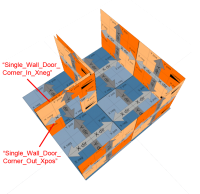
Replacing wall sections with ones containing doors can connect these two areas. Simply select the wall piece to be changed into a door, right click and select “Find in Content Browser...” This will automatically highlight the selected mesh within the various subgroups in the Content Browser. Simply select the nearest “door” subgroup, select the corresponding door piece and replace the existing wall mesh as above. For example, using “Find in Content Browser” on a “Single_Wall_Corner_Out_Xpos” piece highlights the mesh within the “Base” subgroup of the “corner_out” subgroup within the “corner” subgroup of the “Wall” group of the Modular Static Set package. Selecting the “door” subgroup under “corner_out,” one can replace the “Single_Wall_Corner_Out_Xpos” mesh with the “Single_Wall_Door_Corner_Out_Xpos” or the “Single_Wall_DoubleDoor_Corner_Out_Xpos” mesh. The same technique can be used to replace the “Single_Wall_Corner_In_Xneg” mesh on the opposite side (see Fig. 14.)
Doors
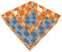
This technique can be used to place doors all over your map (see Fig. 15.). Ceiling meshes can be placed in a similar fashion to floor meshes. Simply duplicate a floor mesh as above and replace it with a basic ceiling piece (i.e,. 'Env_Modular_StaticSet_MESH.single_mesh. Ceiling.Base.Single_Ceiling') from the Content Browser. Then, duplicate the ceiling mesh using the Alt key+drag “Translation Mode” widget as before.
Advanced Examples
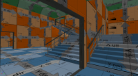
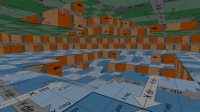
Eventually, you may want to transition vertically. For example, you may want to create a multistoried map with stairs or ramps connecting the various levels. There is a demonstration map named “Mod_Tools_ Demo_Map” that has, among other things, examples of straight stairwells, a stairwell that turns at a right angle and a switchback stairwell (see Fig. 16.). Use this map for ideas on how to use the various stair meshes, ramp meshes, the extensive railing kit as well as other supporting Modular Static Set pieces used in conjunction with stairs.
Stairs
Another method of transitioning vertically is to use a doorway piece to transition into a multistory room. A doorway can bridge two rooms of any height and width, assuming the floor levels are the same (see Fig. 17.). This example consists of a single wall height corridor which opens into a two-story level room.
Multiple Stories
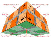
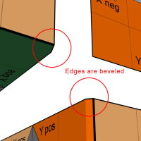
Finally, yet another method of transitioning vertically is to use a ceiling mesh that connects to a wall mesh (i.e., convex “corner up”) or a floor mesh that connects to a wall mesh (i.e., convex “corner down”). In order for a ceiling to connect to a wall, a beveled ceiling mesh must be selected (i.e., within the “bevel” subgroup under the “Ceiling” group) with a bevel along the edge connecting to the wall (see Fig. 18.). The bevel is required to account for the offset between the ceiling, floor and walls.
When creating a “corner out” in conjunction with a “corner up” and/or “corner down,” a beveled wall mesh must be used as well to ensure that all edges will line up appropriately when snapped into place (see Fig. 19.).
Using these pieces, rooms of various sizes can open up to larger areas (or shrink to smaller ones), changing the elevation of both ceiling and floor heights. For example, without using a doorway, a simple single story corridor can open up into a multistory room (see Fig. 20.). Combinations of these meshes can be used to create changes in elevation in almost any direction (see Fig. 21.).
Advanced Modular Static Set Pieces
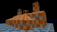
Beyond the basic kit pieces discussed previously, there are additional pieces used to create more complex or specialized areas. For example, the Angle45 Wall, Ceiling and Floor pieces can be used to create rooms with diagonal walls and angled corridors. Due to the elongation of the angled wall stretching the square format of the UVs, the decision was made to retain the correct proportion and density of the UVs with the caveat of having seams at each end of the diagonal wall. Thus, to minimize seams, custom Angle45 meshes for various lengths have been created. Examples of many of these advanced Modular Static Set pieces can be found in the “Mod_Tools_ Demo_Map” mentioned earlier (see Figs. 22.-24).
